Citroen Relay Fuse Box Diagram 2004
Citroen C4 – fuse and relay
I generation Citroen C4 was produced in 2004, 2005, 2006, 2007, 2008, 2009 and 2010 in various versions: hatchback, picasso, etc. After the update, the Citroen C4 II generation was produced in 2011, 2012, 2013, 2014, 2015, 2016, 2017, 2018, 2019, 2020. We will consider the fuses and relays of the Citroen C4 with a detailed description of all boxes and their location. Note the cigarette lighter fuse.

Depending on the configuration and the year of manufacture, several options for the execution of boxes and the placement of the relay are possible.
Contents
- 1 Engine compartment
- 1.1 Main fuse box
- 1.1.1 Type 1
- 1.1.2 Type 2
- 1.1.3 Type 3
- 1.1.4 Maxi fuses
- 1.2 Battery fuses
- 1.2.1 Type 1
- 1.2.2 Type 2
- 1.1 Main fuse box
- 2 Passenger compartment
- 2.1 Type 1
- 2.2 Type 2
- 2.3 Relay and fuse box – BFH3
Engine compartment
Main fuse box
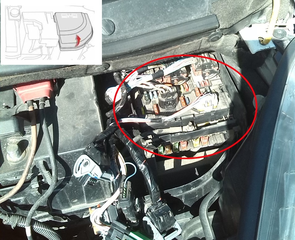
Located next to rechargeable batteries. Detach and remove the protective cover to access the engine compartment fuse box.
Type 1

Diagram
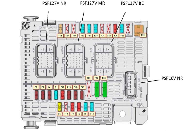
Designation
- F1 15A Engine Control Computer – Power Protection and Distribution Unit
- F2 5A Electric fan group control unit
- F3 5A Engine control computer
- F5 15A Engine control computer
- F6 20A Engine management computer – fuel pump with fuel level sensor
- F7 10A Engine control computer
- F8 10A Engine control computer
- F10 5A Safety contactor for cruise control – automatic transmission computer
- F11 15A Left headlight – right headlight – ionizer
- F14 25A Air conditioning compressor
- F15 5A Power steering pump mechanism
- F17 10A Electrochromic inside rearview mirror – power window / outside mirror control board, driver's door
- F19 30A Low / high speed of the windshield wiper
- F20 15A Windscreen washer pump
- F21 20A Headlight washer pump
- F22 15A Horn
- F23 15A Right headlight
- F24 15A Left headlight
- F26 10A Air conditioning compressor
- F29 30A Starter
The following fuses are located separately (on the underside of the unit):
F10 5A Automatic transmission control group
F11 5A Shift-lock relay
F12 15A Automatic transmission computer
Type 2

Diagram

Circuits protected
- 20 A Engine control, engine cooling fan
- 15 A Buzzer
- 10 A Windscreen and rear window washers
- 20 A Headlight washer
- 15 A Fuel pump
- 10 A automatic transmission, xenon lamps, controlled headlights, adsorber bleed solenoid valve
- 10 A ABS / ESP calculators, power steering
- 25 A Starter
- 10 A Additional heating unit (diesel engine), coolant level sensor
- 30 A Engine solenoid valve, water-in-fuel sensor, engine calculator, injectors, ignition coil, lambda probe, adsorber bleed solenoid valve (vehicles with 1.4i 16V and 1.6i 16V engines)
- 40 A Blower fan, air conditioning
- 30 A Front wiper
- 40 A BSI unit
- Not used
- 10 A Right high beam headlamp
- 10 A Left high beam headlamp
- 15A Left low beam headlamp
- 15A Right-hand dipped beam headlamp
- 15 A Engine calculator (vehicles with 1.4i 16V and 1.6i 16V engines)
- 10 A Engine solenoid valves
- 5 A Relay for the electric fan of the engine cooling system, variable valve timing system
Type 3
Diagram
Assignment
- (20A) (Engine control module – Engine fan group).
- (15A) (Beep).
- (10A) (Front and rear washers).
- (20A (Headlight washer).
- (15A) (fuel pump).
- (10A) (Automatic gearbox – Xenon – Headlights – Absorber cleaning solenoid valve (2.0 engine).
- (10A) (ABS / ESP control units – Power steering).
- (20A) (Starter).
- (10A) (Auxiliary heating control unit (diesel) – Coolant level contactor).
- (30A) (Engine solenoid valve – Water in diesel fuel sensor – Engine control unit – Injectors – Ignition coil – Oxygen sensor – Absorber cleaning solenoid valve (engines 1.4 and 1.6).
- (40A) (Air Fan – Air Conditioning).
- (30A) (Front wiper).
- (40A) (Intelligent breakout box).
- (30A) (Air compressor (on 2.0 engine).
Maxi fuses
These fuses are in the form of fusible links and are located at the bottom of the box.

- MF1 30 A / 50 A Engine cooling fun
- MF2 30 A Power supply for the ABS / ESP
- MF3 pump 50 A ABS / ESP
- MF4 80 A BSI
- MF5 unit 80 A BSI
- MF6 unit 10A Passenger compartment fuse box
- MF7 20 A Diagnostic connector / Pump for Diesel fuel additive
- MF8 Not used
Battery fuses
Photo for example of execution

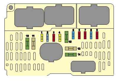
Type 1
Diagram

Designation
| 1 | – |
| 2 | – |
| 3 | (5A) Battery condition sensor |
| 4 | (5A) Transmission control module (ECM) |
| 5 | (5A / 15A) Diagnostic connector (DLC) |
| 6 | (15A) Transmission control module (ECM) |
| 7 | (5A) ABS ESP control unit |
| 8 | (20A) Rear 12V socket |
| FL9 | (60A) Fuses on BSI (Intelligent Power Distribution Module) |
| FL10 | (80A) Power steering |
| FL11 | (30A) Transmission control module (ECM) |
| FL12 | (60A) Cooling fan motor |
| FL13 | (60A) Fuses on BSI (Intelligent Power Distribution Module) |
| FL14 | (70A) Glow plugs |
| FL15 | (100A) Relay protection relay box 3 |
| FL16 | – |
Type 2
Diagram
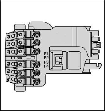
Appointment
- F1 Not used
- F2 30 A Transmission (mechanical with electronic control or automatic transmission)
- F3 Not used
- F4 Not used
- F5 80 A Power steering pump
- F6 70 A Heating unit (diesel engine)
- F7 100 A Protection and switching unit
- F8 Not used
- F9 30 A Electric pump assembly for an electronically controlled manual transmission
- F10 30 A Valvetronic motor
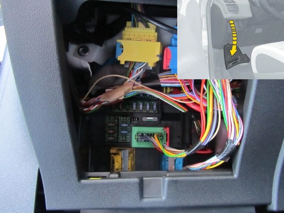
Passenger compartment
Fuse box is located to the left of the driver under the dashboard. Access to them is closed by a decorative cover. In order to open this cover, you need to: release the latches, for which pull it by the upper part, then remove the cover by turning the 2 bolts 1/4 turn, and fold the box. A special tweezers are fixed on the back of the frame, with which you can easily dismantle any fuse.
Type 1
Diagram
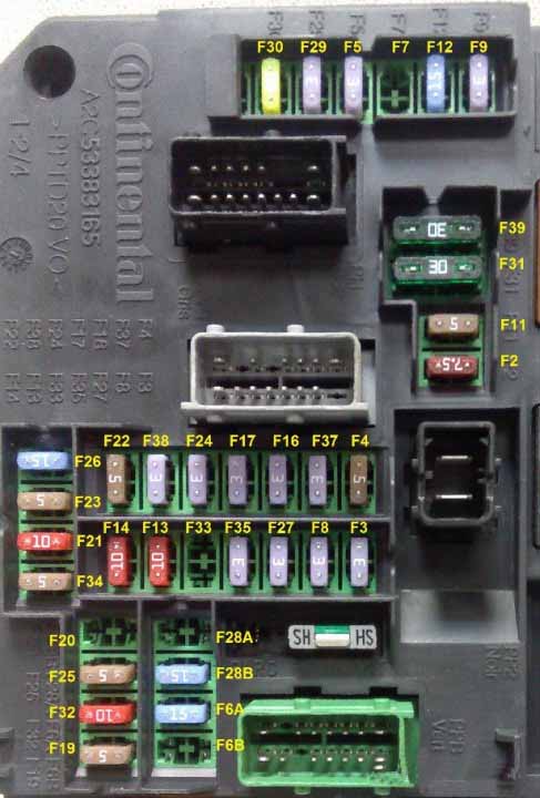
Designation
F2 7.5A Diagnostic connector.
F3 3A Anti-theft device or START / STOP button.
F4 5A Reader for remote control key.
F5 3A Remote control key.
F6A-F6B 15A Touchscreen display, audio and navigation system, CD player, USB and additional connectors.
F7 15A Hands-free start assist electronics
F8 3A Burglar alarm siren, alarm processor
F9 3A Steering wheel switch box
F11 5A Stability calculator, common alarm switch box, electronic key scanner
F12 15A Double contactor brake pedals
F13 10A Front cigarette lighter
F14 10A Rear cigarette lighter.
F16 3A Individual lights, glove box lighting.
F17 3A Sun visor illumination, individual lamps.
F19 5A Instrument panel.
F20 5A Electronically controlled manual transmission gear selector.
F21 10A Car radio and air conditioning control.
F22 5A Displays, parking sensors.
F23 5A Engine compartment fuse module.
F24 3A Rain and light sensor.
F25 15A Block of airbags and pyrotechnic tensioners.
F26 15A
F27 3A Double brake pedal contactor.
F28A-F28B 15A Car radio, autoradio (optional).
F29 3A Steering column switch.
F30 20A Rear window wiper.
F31 30A Central locking, front and rear external and internal locks.
F32 10A Power supply for rear view camera in C4L China. (16V NE 13pin output), audio amplifier.
F33 3A Driver's seat memory unit.
F34 5A Power steering relay.
F35 3A
F37 3A Driver's door wiper / rearview mirror control – Electro chrome interior rearview mirror
F38 3A Headlight range control switch – Electro chrome rearview mirror.
F39 30A
The fuses are responsible for the cigarette lighter – 13 and 14.
Type 2
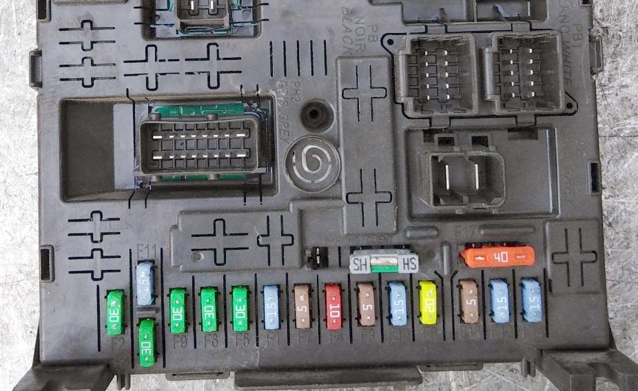
Diagram

Assignment
- F1 (15A) Rear windscreen wiper.
- F2 (30A) Central locking – Super locking.
- F3 (5A) Airbags and pretensioners.
- F4 (10A) Diagnostic connector – Brake light switch – Electrochromic rearview mirror – Dynamic stability control (ESP) – Water level sensor – Diesel fuel additives – Clutch pedal contactor (ESP, cruise control and speed limiter.
- F5 (30A) Front power windows – Heated and power mirrors.
- F6 (30A) Rear power windows.
- F7 (5A) Interior lighting.
- F8 (20A) Car radio – NaviDrive – Steering wheel controls – Display – Security alarm – Front 12V socket – Trailer connector – Driving school module.
- F9 (30A) Cigarette lighter – Rear 12V socket.
- F10 (15A) Tire pressure sensors – BVA – STOP contactor.
- F11 (15A) Anti-theft steering lock – Diagnostic connector – Diesel particulate filter.
- F12 (15A) Electric seat adjustment – Signal warning of unintentional crossing of the lane line – Parking sensors.
- F13 (5A) Rain sensor – Light sensor – Electronic manual transmission – Engine control unit.
- F14 (15A) Air conditioning – Instrument panel – Tachometer – Airbags and pretensioners – Trailer connector – Bluetooth telephone.
- F15 (30A) Central locking – Super locking.
- F16(SHUNT)( – ).
- F17 (40A) Heated rear window.
- F29 (20A) Heated seats.
- F33 (4A) Parking aid, automatic wiper and lighting.
- F36 (20A) Hi-fi amplifier.
- F37 (10A) Air conditioning.
- F38 (30A) Power driver's seat.
- F39 (5A) Filler flap.
- F40 (30A) Power passenger seat, panoramic roof.
The fuses number 8 and 9 are responsible for the cigarette lighter.
Relay and fuse box – BFH3

Located just below the main one.

Protected components
| F3 | 15A compartment fuse box 5 for taxi version |
| F4 | 15A 12V socket for multimedia equipment |
| F5 | 30A electric motors for rear window lifts |
| F6 | 30A electric motors for front glass lifters |
| F7 | 2A heated seats |
| F8 | 20A air conditioner fan |
| F9 | 30A electric tailgate |
| F10 | 40A left seat belt reel |
| F11 | 5A trailer switching unit |
| F12 | 30A electric driver seat and massage device |
| F13 | 40A right seat belt reel |
| F14 | 30A Reinstalling Handle – Power Passenger Seat – Seat Massage Devices |
| F15 | 25A electric sunroof blinds |
| F16 | 5A multiplex control board glass lifter / door mirror driver's door |
| F17 | 10A unit of illumination and memory of the position of external rear-view mirrors |
| F18 | 25A audio amplifier |
| F19 | not used |
| F20 | 7.5A electric tailgate |
| F21 | 3A "Hands free" access and start unit |
| F2 | 7.5A electrically heated mirrors |
| F22 | 20A socket 230V |
| F23 | not used |
| R1 | 230V socket |
| R2 | 12V connector |
| R3 | not used |
| F1 | 40A rear window heating |
Individual elements of relays and fuses can be installed outside these units, and are located next to their protection device (for example, cooling fan relays, etc.)
We have posted a video on our YouTube channel. Watch and subscribe.
If you know how to make your article better, write in the comments.
We use cookies on our website to give you the most relevant experience by remembering your preferences and repeat visits. By clicking "Accept", you consent to the use of ALL the cookies.
Posted by: phyllisgratchimeso.blogspot.com
Source: https://fuseandrelay.com/citroen/c4.html

Posting Komentar untuk "Citroen Relay Fuse Box Diagram 2004"